TEC-503
Furnace LCM4 Controller Setup & Installation
![]()
1.0 Scope
1.1 Instructions for the setup and installation of the SNAP-LCM4 Controller on an IR furnace. Applies to all FurnacePros, RTC Radiant Technology, and GreenBridge Technology furnaces with Opto22 control systems.
2.0 Equipment Affected
2.1 Snap LCM4 Furnace Controller.
2.2 Power Supply, 5 Vdc
3.0 Configuration
3.1 3.1 Remove blank plate and install M4SENET-100 Ethernet card in any empty slot of the LCM4 controller
3.2 Remove serial card and verify that the jumper settings are as below. Replace serial card.
3.3 Verify jumper settings on LCM4 Faceplate.
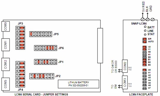 |
| Figure 3.3.1 LCM4 Furnace Controller Jumper Settings |
4.0 Installation
4.1 Mount LCM4 horizontally or vertically in a secure location close to 5 Vdc power supply.
4.2 Connect LCM4 to a dedicated 5 Vdc power supply. Supply voltage should be maintained at between 5.1 Vdc -5.2 Vdc.
4.3 Connect the supplied tantalum capacitor across the 5 Vdc and Common terminals of the power supply dedicated to the LCM4 Controller. CAUTION: The power supply used for the SNAP-LCM4 should not be used to supply any other equipment. Field devices must not be supplied by the same power supply used for the controller, as the optical isolation of the I/O modules would be bypassed and the voltage fluctuations to the controller might cause controller resets.
4.4 Connect cable from G4IOR interface or B3000 or B3000-B brain to COM2.
4.5 If equipped with a serial element monitoring system (EM), connect EM cable to COM3.
4.6 Connect Ethernet TCP/IP cable to M4SENET-100 card if so equipped.
5.0 Battery
5.1 The Opto22 LCM4 controller has a lithium backup battery with a 5-year life cycle, but other factors may affect its service time. Storing the unit with the furnace power off shortens the battery lifespan. The battery will actively back up RAM when the Furnace is OFF. When the battery is near the end of its useful life the BATT LED will turn red. Once the battery begins to fail, the furnace controller will often fail to retain program parameters after power is lost to the controller. Eventually the program may not reset or may fail to load. BATT LED is normally green.
5.2 If the battery fails replace with part number 322-092208-01.
6.0 Troubleshooting
6.1 Use the following table to troubleshoot Opto22 PLC communication problems:
| Table 6.1 PLC Opto22 Troubleshooting Guide; | ||||
| Indication | Explanation | Remedy | ||
|---|---|---|---|---|
| LINE LED is OFF | No Power. | Check wiring. | ||
| LIINE LED is red or Controller resets. | Power may be out of specification | Check the power supply for 5V DC power. | ||
| STAT LED is OFF | Controller is faulty | Call FurnacePros Technical Support. | ||
| STAT LED blinks red | Firmware problem | Call FurnacePros Technical Support. | ||
| BATT LED is red | Backup battery is low | Replace LCM4 controller battery. | ||
| RX LED is stuck ON | Wiring polarity problem | Call FurnacePros Technical Support. | ||
| Controller cannot transmit to PC | Configuration jumpers were changed without cycling power. | Cycle power off/on and retry transmission. | ||
| No communication to host PC. | Communication Problems | Check serial port. Check PC IP address (10.192.105.100) | ||
| No communication to host PC. RX LED is ON, but TX LED is OFF | Communication Problems | Check controller address (10.192.105.102), baud rate, and ASCII/binary settings. | ||
| No communication to host PC. RX and TX LEDs are ON | Communication Problems | Try a slower baud rate. | ||
| No communication to I/O modules. TX LED is OFF while trying to communicate. |
Communication Problems | Check that I/O port software is configured for correct port. If RX LEDs on I/O modules are off while trying to communicate, check for loose connections, shorts or breakage. IF RX LEDs on I/O are on, check I/O address, baud rate, and protocol setting in software. |
||
| Furnace program fails to load with correct parameters, clock is wrong, or furnace controller fails to reset. | Backup battery is low (battery has a 5 year life cycle) | Replace LCM4 controller battery. | ||